3D Boxes
The 3D Box Tool draws three-dimensional boxes that maintain their perspective when moved over the canvas. A 3D box is composed of an SVG Group consisting of six closed paths shaded to give the illusion of a three dimensional shape.
3D Box Options
With Inscape 1.5 the 3D-box tool has three choices in the Preferences dialog for how style is inherited.
Last used style: The 3d box group inherits the current style from the last changed object (in particular, all the faces have the same color - no 3d appearance with this option).
Object type’s last used style: (This is the default behavior.) - Faces initially have 3D shading, but changes are inherited by a subsequently drawn 3D box.
The Tool’s own style: The default behavior is to always draw a 3D shaded box.
More details about these options are given later.
The instructions given below refer to using Preferences choice 2 (with 3d shaded box faces).
Create a 3D Box object
Select the 3D Box tool from the Toolbox on the left side of the window (keyboard shortcut ShiftF4).
Left mouse drag over the canvas. Where the drag starts will be one corner of the front x-y face. And where the drag ends will be the opposite corner.
It is best when first drawing a 3d box to do it somewhere inside the page border. The 3d box can look rather distorted when drawn near the edges or off the page border.
Press Shift at any time after you start drawing the 3D box to extrude it along the z-axis.
3D Box Tools’ Control bar

First drawn 3D box defaults with these values
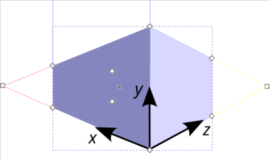
Angle X:30 greyed out, Angle Y:270 infinite vanishing point, Angle Z:30 greyed out
Vanishing points are the points where the red and yellow lines converge, to create a 3D effect of a horizon, on a 2D canvas.
The X and Z vanishing points are square handles placed midway down on the left and right edges of the page.
Basic Modifications
With the Select tool selected
The 3D box can be modified using the transformation handles (See Transformation handles )
With Node tool and other Shape tools selected
It is possible to select 3D-box faces inside the 3D-box group
Zero-point perspective (Isometric Projection)
With a 3D-box already drawn
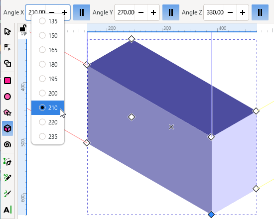
Select each of the || buttons to set each of the orientation angles’ vanishing points to infinity. Keyboard shortcuts: ShiftX, ShiftY, ShiftZ.
Enter these values: Angle X:210, Angle Y:270, Angle Z:330. This produces an isometric box.
After you click the || button, you can right-click on the spinbox, to see a menu of useful angles.
Entry box arithmetic (+ add, - subtract , * multiply , / divide) is possible. Computation progresses from left to right.
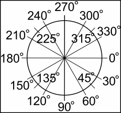
The diagram on the right shows the angle directions relative to the page.
Modify the Isometric Box using mouse
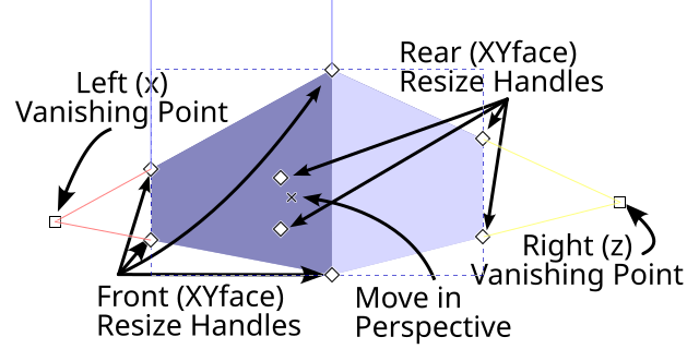
Any of the four front face diamond handles can be dragged along the red (x) or blue (y) directions.
The four rear face diamond handles can only be dragged in the yellow (z) direction.
Hold Shift to switch the freedom of movement directions of the front and rear faces.
Hold CtrlCmd to restrict movement of resize handles to lines along the box’s edges or to a diagonal direction. This allows adjusting just one dimension of a box face in the first case or keeping the aspect ratio fixed in the latter case.
Drag the central x handle to move the whole box, while keeping the vanishing points in the same place. This allows the box to have the proper 3D-simulated perspective, no matter where it is moved.
The 3D-boxes are shaded as if illuminated from a light source positioned lower right.
Examples of modification
Drag the rear XYface forward along yellow (z) axis, to pass through front XYface. This gives the illusion of turning the 3D box inside-out. The former rear XYface now appears invisible. The top XZface appears semi-transparent (Note that this is the appearance only. No changes have occurred to the face fill values). Drag the right YZface through left YZface, bottom and top faces now appear invisible when viewed from outside. Various “pass through” actions, such as were just described, can produce a variety of shading combinations. Have fun testing!
Modify the Isometric 3D Box using the keyboard
While it is possible to move the 3D box handles with the arrow keys, it is Not recommended. (This is because the movement can be unpredictable.)
When the vanishing points are set to infinite, the angle values can be increased or decreased in increments (15° by default, see Rotation snap angle)
[ or ] keys for x direction:
( or ) keys for y direction:
{ or } keys for z direction:
Hold AltOption to reduce changes to just 0.5°.
Some useful angles for common parallel-sided projections:
1-point Perspective:
After drawing a 3D box:
Set the X and Y vanishing points to infinity (by enabling the || button for each).
Enter Angle X: 180 and Angle Y: 270
Deselect || for Z (this will gray out the Z spinbox).
Examples
Construct a street with multiple 3D-box buildings on both sides, diminishing to a common horizon point.

Holding the Shift key while dragging the “in perspective handle” x, constrains movement along the yellow (z) axes.
Draw the interior of a room or tunnel.
Drag the yellow (z) vanishing point square handle close to the center x handle of a 3D box.


Select the front XYface and delete it (steps described later, Selecting faces within the 3D box group). Now we can see the interior of the 3D box, which can look like a room or tunnel.
Alternatively, the rear XYface can be dragged forward until the box appears to be inside-out (No need to delete a face.) This produces a different shading arrangement.
New 3D boxes will share the same vanishing points as the last one drawn or last one selected.
To separate shared vanishing points for selected 3D boxes, hold the Shift key while dragging a vanishing point handle. (Also, selecting a 3D box with the Select tool and moving the 3D box will break away its vanishing points.) To merge a separated vanishing point handle with another vanishing point handle, hold Shift and select both 3D boxes, then place the vanishing points in close proximity to each other.
Warning
Separating vanishing points will result in unselected 3D boxes reverting to 2-point perspective boxes with their vanishing points mid way on the pages edges. Work around - copy and paste 3D box. (Merge request 7478 could fix this.)
2-point Perspective:
This is the 3D Box Tool’s Default perspective.
Example
Moving duplicates (CtrlCmdD) of a 3D box to create stacked boxes.
To move along yellow z lines, hold the Shift key while dragging the ‘in perspective’ (x) handle.
To move along red x lines, hold the CtrlCmd key while dragging the ‘in perspective’ (x) handle.
(A box that’s being dragged will also jump to align with faces of other nearby 3D boxes.)

New 3D boxes will share the same vanishing points as the last one drawn or last one selected. (See separating vanishing points)

3-point Perspective:
All three vanishing points are enabled by disabling all three parallel line buttons ||. This is useful for drawing a large tower or column.
New 3D boxes will share the same vanishing points as the last one drawn or last one selected. (See separating vanishing points)
Change the appearance of 3D Boxes
Change the default face positions or delete a face
Selecting faces within the 3D box group
A normal group can be entered by double-clicking the group, but in this case double-clicking a 3D box activates the 3D box tool.
Instead, try one of these three options:
Choose ‘Enter Group’ from the context (right-click) mouse menu.
Choose a face from the Layers and Objects dialog.
Click on a 3d box with any other shape tool, to select a face.
Click to select visible faces
AltOptionClick to select hidden faces
In addition holding the Shift key allows selection of multiple faces.
Change to the Select tool . Now you can move the face as desired. For example move all the faces outwards to produce an exploded/opened view of a 3D box.
To delete a face, select it and press Del. For example, delete a front face to see the interior of a 3D box.
Note that neither moving a face or deleting a face affects 3D boxes that are subsequently drawn with the 3D Box tool.
Changing the default 3D box face colors
Note
To revert to the original default 3d shading, the preferences.xml file can be either edited or reset.
(If you decide to reset all your preferences, be sure to make a copy of preferences.xml first!)
There are two general ways to approach changing the default colors of the 3D box faces: change the style of the group, or change the style of the individual faces. The next sub-sections explain the details.
Change the style of the group
To change the style of a 3D box, select it with Selection tool . Then use the Fill and Stroke dialog, or click in the Palette, to change the fill color. Note that all six sides of the 3D box will become the same color that you clicked. This technique does not create the 3D illusion. The next section below, Change the style of individual faces, explains how to do that.
If you want the next 3D box you draw to use the current style, then go to , and tick the ‘Last used style’ option.
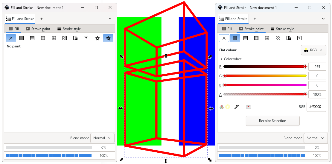
You can create a “wireframe” appearance by adding a stroke (if there is not one already): second from the left. And then remove the fill: top-left.
Individual face colors can be changed, and the last face changed will become the new current style for subsequently drawn 3D boxes. Also, these individual face style changes will be inherited, if you change , to ‘Object type’s last used style’. See the next section for more about changing face colors.
Change the style of individual faces
If you want the next 3D box you draw, to have the same color faces as the last object you drew, then go to and tick the ‘Object type’s last used style’ option. This option most closely matches the default behavior in earlier versions of Inkscape.
Initially, by default blue 3d-shaded 3D boxes will be drawn, however, changes to any 3D box face styles will be inherited in option 2 by any newly drawn 3D box. And as we’ve learned, if you click in the palette while a 3D box is selected, all the faces of that box will change to the color you clicked. So it is quite easy to loose the original 3d shading in subsequently drawn 3D boxes.
With this option you are free to change face styles. Select a 3D box face ( selecting group objects described earlier) then change the color (e.g. using Fill and Stroke dialog or color Palette). Plus, the style attributes of stroke, and alpha transparency can also be applied.
Newly drawn 3D boxes will now inherit these new face styles.
Note
If retaining the 3d shading is important, consider using the third option ‘The Tool’s own style:’.
Tip
If you should want to restore the original default blue-shaded appearance of 3D boxes, here are those colors. You just need to select each face as indicated, and change the color using the Fill and Stroke dialog > Fill tab.
XYfront |
8686bf |
XYrear |
e9e9ff |
XZtop |
4d4d9f |
XZbottom |
afafde |
YZright |
353564 |
YZleft |
d7d7ff |
Your own box style
The third option for giving 3D boxes a style when you draw them, is ‘This tool’s own style:’. If you have a preferred 3D box style that will be created each time and ignore any modifications made, this is the option to use.
By default it draws blue 3D-shaded 3D boxes, and will continue to do so until an alternative style is saved with the Take from selection button.
For example, changing the 3D-shaded color. If you want to maintain the original 3D shaded appearance of the box, choose HSLuv from the style of color selection menu, in the Fill and Stroke dialog. Then change only the Hue value, using the same value for each face. (Default blue shade HSLuv Hue: 266°)
After creating your preferred 3D box coloration, click once with the Selection tool. Then go to , choose the option ‘This tool’s own style:’ and click the Take from selection button. The change is recorded.

Tip
Create a collection of different 3D boxes with colors that you often use, in a special SVG file. Now when required, you can copy and paste the desired color 3D box into a working file. The colors are now part of that document’s XML and will not affect preferences.xml. They will otherwise behave as normal 3D boxes.
Adjustments with Object Properties dialog
Todo
Revisit this later, when Object Properties chapter has been written [No object properties currently]
Modify/view with XML Editor
Example: 3D Box group
Name |
Value |
units in mm (millimetres) |
|---|---|---|
inkscape:corner7 |
0.064218452 : 0.072793726 : 0.43540449 : 1 |
|
inkscape:corner0 |
0.38372294 : 0.12050361 : 0 : 1 |
|
inkscape:perspectiveID |
#perspective16 |
|
style |
fill: #00ff00;…. |
CSS style properties |
id |
g16 |
|
sodipodi:type |
inkscape:box3d |
Corresponding <defs >
<inkscape:perspective id=”perspective16”>
Name |
Value |
units in mm (millimetres) |
|---|---|---|
id |
perspective16 |
|
inkscape:persp3d-origin |
105.83334 : 105.83333 : 1 |
|
inkscape:vp_z |
211.66667 : 158.75 : 1 |
Vanishing points |
inkscape:vp_y |
0 : 1000 : 0 |
x:y:0(parallel),1(converge) |
inkscape:vp_x |
0 : 158.75 : 1 |
|
sodipodi:type |
inkscape:persp3d |
Example: One of the 3d Boxes’ face paths
Name |
Value |
units in mm (millimetres) |
|---|---|---|
points |
93.299577,44.784609 137.9…. |
|
d |
M 93.299577,-2.9252751 V…. |
SVG path |
inkscape:box3dsidetype |
14 |
|
style |
fill: #d7d7ff;fill-rule:…. |
CSS attributes |
id |
path19 |
|
sodipodi:type |
inkscape:box3dside |
In Inkscape, the 3D Box tool utilizes Sodipodi attributes to define group and face properties. These parameters are stored using XML attributes prefixed with sodipodi: and inkscape: within the Inkscape SVG code.
When the SVG is loaded into Inkscape these attributes are used to regenerate the SVG path d=”” attributes.
If exported as Plain SVG only the path will be saved (same as if Object to Path were applied). If the same Plain SVG file were loaded into Inkscape, the original 3D box will no longer be editable using the 3D Box tool, because it had been changed into a regular path.